Blog

Methods to Make ESP32 Blinks

Here’s a comprehensive breakdown of all practical methods to blink an LED on an ESP32, categorized by execution model, with framework context, key APIs, and use-case guidance.

Blocking Methods #

Method Framework Key API Notes
Simple Delay Arduino / ESP-IDF delay(500) or vTaskDelay(pdMS_TO_TICKS(500)) Blocks the CPU. Fine for single-task sketches.
Deep Sleep Wake ESP-IDF / Arduino esp_sleep_enable_timer_wakeup(), esp_deep_sleep_start() Not for continuous blinking. Used for ultra-low-power periodic tasks (e.g., sensor + LED indicator).

Non-Blocking / Polling Methods #

Method Framework Key API Notes
millis() State Machine Arduino if (millis() - lastToggle >= 500) { toggle(); } Standard non-blocking pattern. Allows concurrent loops (WiFi, sensors, etc.).
esp_timer_get_time() ESP-IDF uint64_t now = esp_timer_get_time(); Microsecond-precision version of millis(). Used in same state-machine pattern.

Hardware Timer & Interrupt Methods #

Method Framework Key API Notes
Hardware Timer + ISR ESP-IDF / Arduino timer_create(), timer_arm(), attachInterrupt() Uses ESP32’s 4 hardware timers. ISR toggles GPIO. Must be short & marked IRAM_ATTR.
LEDC Peripheral (Hardware PWM) ESP-IDF / Arduino ledcSetup(), ledcAttachPin(), ledcWriteTone() Built-in PWM controller. Can generate exact square waves without CPU. Best for precise 1 Hz.
RMT Peripheral ESP-IDF rmt_init(), rmt_write_sample() Remote control peripheral. Overkill for blinking but can output arbitrary pulse trains via DMA.

FreeRTOS Task & Synchronization Methods #

(ESP32 runs FreeRTOS natively in both Arduino & ESP-IDF)
Interupsi Timer pada ESP32

Contoh program Interupsi timer dengan frekuensi 1 kHz, output ke GPIO nomor 2 Menggunakan Arduino Core versi 3.x (bukan 2.x)

Kode #

// ESP32 - 1 kHz LED Blink via Hardware Timer Interrupt
// Compatible with ESP32 Arduino Core v3.x (new timer API)

#define LED_PIN 0  // Built-in LED on most ESP32 dev boards

volatile bool ledState = false;

hw_timer_t* timer = NULL;

// ISR - fires at 2 kHz, toggles LED → full ON/OFF cycle = 1 kHz
void IRAM_ATTR onTimer() {
  ledState = !ledState;
  digitalWrite(LED_PIN, ledState);
}

void setup() {
  Serial.begin(115200);
  pinMode(LED_PIN, OUTPUT);

  // New API (Core v3.x): timerBegin(frequency_hz)
  // 2000 Hz ISR → LED toggles 2000x/sec → blink cycle = 1 kHz
  timer = timerBegin(2000);

  // Attach ISR
  timerAttachInterrupt(timer, &onTimer);

  // Alarm every 1 tick at 2000 Hz = every 500 µs
  timerAlarm(timer, 1, true, 0);

  Serial.println("1 kHz LED blink started (Core v3.x API).");
}

void loop() {
  // Main loop is free — all work done in ISR
  delay(1000);
  Serial.println("Running... LED blinking at 1 kHz.");
}

Referensi #

ESP32 Dengan Antar Muka LCD GC9A01

Komponen #

Komponen yang dipakai adalah sebagai berikut:

  • ESP32 Lolin32 Lite
  • Modul GC9A01

Fungsi pin pada GC9A01 #

Modul GC9A01 yang dipakai memiliki pin sebagai berikut:

  • RST : reset
  • CS : chip select
  • DC : data/command select
  • SDA : data SPI MOSI. Namanya (SDA) seperti pin pada protokol I2C, namun sebenarnya display ini menggunakan protokol SPI
  • SCL : clock SPI
  • GND : ground
  • VCC : 3,3 volt

Dari hasil percobaan, pin RST tidak perlu dihubungkan

ESP32C6 Mini

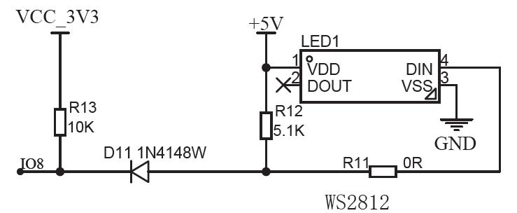
Demo lampu kedip pada ESP32C6 Mini menggunakan LED RGB onboard

Kode #

#include <Adafruit_NeoPixel.h>
constexpr uint8_t LED_PIN = 8;
constexpr uint8_t NUM_LEDS = 1;
Adafruit_NeoPixel rgbLed(NUM_LEDS, LED_PIN, NEO_GRB + NEO_KHZ800);
struct RGB {
    uint8_t r, g, b;
};

constexpr RGB COLOR_OFF   = {0, 0, 0};
// ...Feel free to add more colors here...
constexpr RGB CUSTOM_COLOR = {255, 0, 255}; 

void setColor(const RGB& color, uint8_t brightness = 100) {
    uint16_t scale = (uint16_t)brightness * 255 / 100;
    uint8_t r = (uint8_t)(((uint16_t)color.r * scale) / 255);
    uint8_t g = (uint8_t)(((uint16_t)color.g * scale) / 255);
    uint8_t b = (uint8_t)(((uint16_t)color.b * scale) / 255);
    rgbLed.setPixelColor(0, rgbLed.Color(r, g, b));
    rgbLed.show();
}

void setup() {
    rgbLed.begin(); 
    rgbLed.show(); 
}

void loop() {
    setColor(CUSTOM_COLOR, 50); // 50% brightness
    delay(1000);
    setColor(COLOR_OFF);
    delay(1000);
}

Referensi #

ESP32C6 Mini

ESP32C6 Mini dari WeAct Studio

Skema Rangkaian #

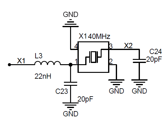
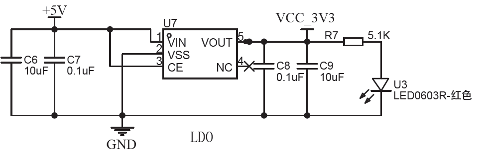
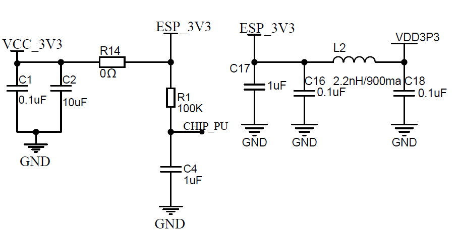
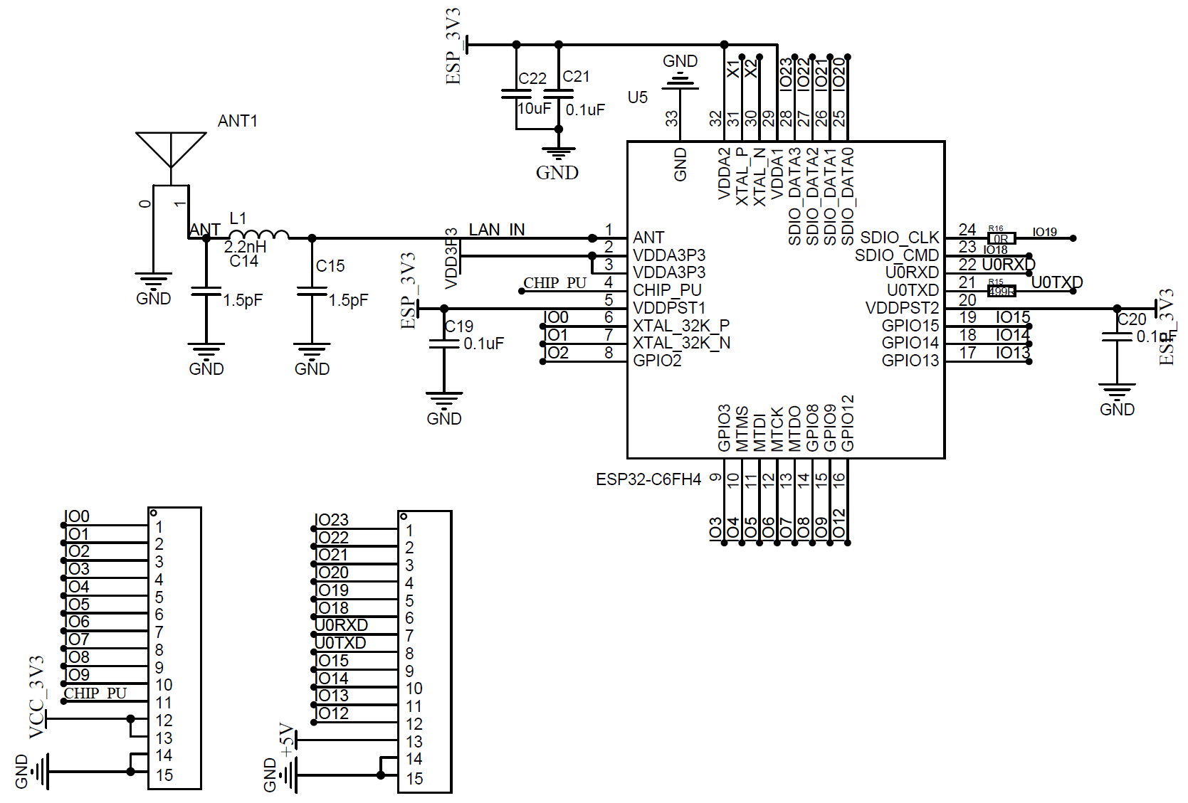
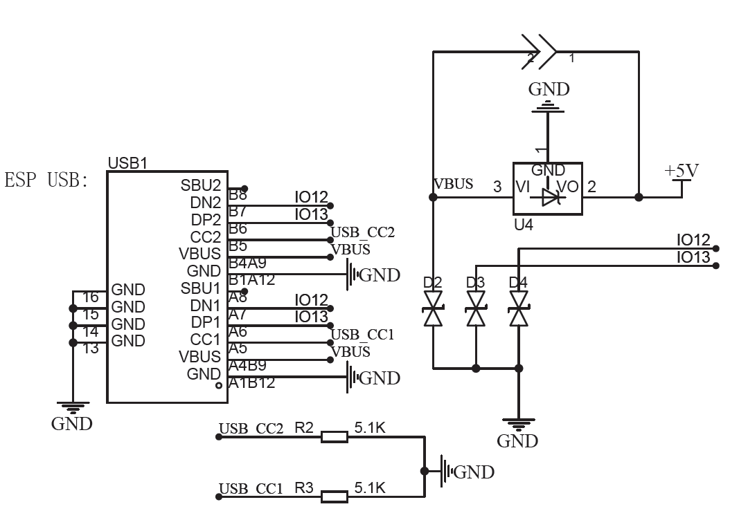
Skema rangkaian lengkap di : https://github.com/WeActStudio/WeActStudio.ESP32C6-MINI/blob/main/Hardware/ESP32_C6_MINI_Sch.pdf

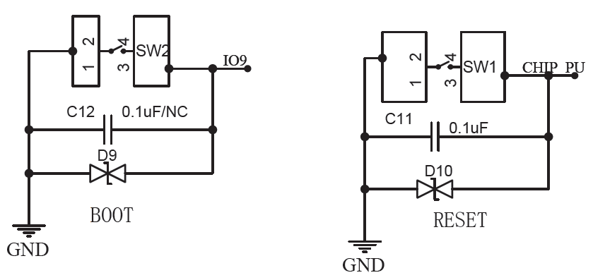
Berikut ini rangkaian switch boot dan reset

alt

alt

alt

alt

alt

alt

alt

Deskripsi Pin #

Deskripsi pin dapat dilihat di https://docs.espressif.com/projects/esp-dev-kits/en/latest/esp32c6/esp32-c6-devkitc-1/user_guide.html Ada beberapa pin yang memiliki fungsi khusus pada waktu booting: MTMS (GPIO3), MTDI (GPIO4), GPIO8, GPIO9, GPIO15

Referensi #